Abba Enterprises Abba Enterprises Abba Enterprises cable wires
wire lab equipments cable wires
company profile product & services site photographs contact us home
 
  Traverse Systems Principle Of Operation Traverse Assembly  
  Application Areas Selection Of Traverse Unit Operational Guide  
  Techical Specification & Dimension Vertical Application Optional Features  


1) Model
2) Shaft rotation Top towards or Top away.
Note: Traverse unit can be easily altered to suit required direction of rotation of the shaft at site.


3) Optional Accessories / Features
1) Free movement lever
Type 1 (Free movement lever provided on bottom side)
Type 2 (Free movement lever fitted on top side)
2) Remote control of Traverse pitch
3) Pitch setting by set screws
4) Reversal slow down
5) Pneumatic reversal


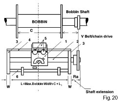
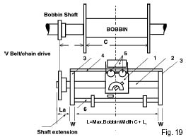
1. Traverse Unit
2. Hardened and Ground Shaft
3. Side Brackets
4. Steady Rail
5. Wire Guide Roller Assembly / Wire Guide Pulley
6. Reversal end Limit Adjustments


I. Max Traverse stroke required or shaft length L required between two side end brackets.
II. Required length of shaft extension and Shaft Extension required on right side Ra or left side La Ra- Extension beyond right hand bracket when looking at the pitch selection scale. La- Extension beyond left hand bracket when 

looking at the itch selection scale.
III. Direction of shaft rotation while providing the drive  (refer fig)
IV. Requirement of Load carrier
    a) Bearing mounted
    b) With linear bearings
    c) With LM Guides
    Note: Traverse assembly is normally offered with bearing mounted load carrier unless specified.
V. Requirement of wire guide pulley or / guide rollers.
VI. Optional features / Accessories
    a) Bellows
    b) Tapered winding by self adjusting end stops for bi-conical and conical spools
    c) Lead screw operated end stops
    d) Built in speed reduction gear box


All Right Reserved @ abbaindia.com. Site designed by Dotcom Services India Pvt Ltd.