 |
 |
 |
 |
| Traverse Systems | Principle Of Operation | Traverse Assembly | |||||
| Application Areas | Selection Of Traverse Unit | Techical Specification & Dimension | |||||
| Vertical Application | Optional Features | Ordering Information |
1) Traverse Shaft: It is recommend to use traverse unit along with hardened and ground finished steel shaft of the following specifications and quality. a) Surface hardness > 45 RC. Case hardened or induction surface hardened. e) Leading end champher: The leading end of the shaft should be chamfered to 300 x 2 mm to avoid damage to the Rolling rings when screwing the unit on to the shaft. |
 |
Shaft Length L:
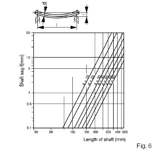
Max Shaft Length: Max traverse stroke is restricted only by max permissible shaft sag. While selecting a suitable model for an application, it is important to consider the maximum traverse stroke required.
|
 |
There is no restriction on minimum stroke length if pneumatic reversal is used.
Assembling The Traverse Unit On To The Shaft.
Adjust pitch setting at 10 on dial.
One end of the shaft is inserted in to the traverse unit slowly and shaft is rotated in correct direction. By rotating the shaft the traverse unit is moved on to the shaft.
When shaft is rotated in correct direction the bearing end of the release lever points towards the direction of travel of the unit.
Removing The Unit From The Shaft: The unit can be removed from shaft by rotating the shaft in opposite direction.
2) Reversal
Instantaneous Reversal: The reversal is instantaneous and automatic. On making contact with end stop, the torsion spring on the reversal mechanism gets charged, trigger, and force the reversal once the throw over position is reached.
For the reversal, system to operate a minimum distance of travel equivalent approximately to diameter of the shaft is required.
The reversal time is pitch related (see fig 6 ). Consequently, as the pitch is increased, there is a very slight increase in traverse stroke length (and decrease if the pitch is reduced). Difference in stroke length also occurs when shaft speed is varied significantly without altering the pitch.
3) Direction of Shaft Rotation and How to Modify Traverse Unit to Suit required Direction of Rotation of Shaft
The reversal mechanism is dependent on direction of shaft rotation. For the reversal mechanism to operate shaft has to be rotated in correct direction of rotation. When shaft is rotated in correct direction the bearing end of the release lever points towards the direction of travel of the unit. If this is not the case, the reversal mechanism can be altered as described below.
Method: The Reversal mechanism is removed, and refitted with a 180 ° turn of the release lever.
|
  |
Pitch Setting lower than '1' in the scale should be avoided if requirement is for a high quality wind. Reduce the Traverse Shaft for optaining lower pitch values.
For applications where minimum to maximum pitch ratio required exceeds 15:1 ,traverse shaft may be provided with two speeds for fine adjustment of pitch and accuracy
5) Shaft Speed:
The required shaft speed N is calculated with reference to max pitch of the traverse unit.

Calculation of Shaft Speed for Winding Applications
(Ref Fig. 3)
Vw: Winding speed m / min
d(mm): Max dia or width of material to be wound or max required pitch S
D (mm): Barrel diameter of bobbin
Optimum Ratio (Kopt) Between Spool Shaft and Traverse Shaft Speed.

6) Mounting Guide Assembly on Traverse Unit:
Guide assembly can be mounted on top mounting surface of Traverse unit.
Ensure to use correct length screws for mounting guide assembly / associated parts on the traverse unit. Excess length bolt if used will cause obstruction to moving parts inside causing difference in linear speeds and may also cause damage to parts inside the unit. Refer dimension details for max screw length N.
The weight of guide assemblies mounted directly on the Traverse unit should be reduced to minimum possible to
maintain accuracy at reversal points.
When heavy guide assemblies are to be traversed or when the tension / twisting forces in the material to be traversed is large or when there is large overhang for the guide assembly, a Load Carrier is recommended for mounting the guide assembly to increase efficiency.

8) Load Carrier - Separately Carried Additional Loads
a) Bearing Mounted: 4 No bearing fitted on to a
separate top mounting plate assembly, used in conjunction with steady bar prevents the rotation of the unit on the shaft and also takes care of twisting forces. Used for moderate loads and twisting forces.
b) With Linear Bearings: Guide assembly is mounted on a load carrier with linear motion bearings and supported on two no guide shafts.
c) With Linear Motion Systems: Guide assembly mounted on a load carrier with LM guides suitably mounted on a machined mounting surface. This system is very effective in traversing heavy loads and also used in application where spool is to be traversed.

9) Side Brackets: To support the shaft on bearings.
10) Steady Rail: Two guide bearings provided
on traverse unit rolls on the steady rail.
| All Right Reserved @ abbaindia.com. | Site designed by Dotcom Services India Pvt Ltd. |